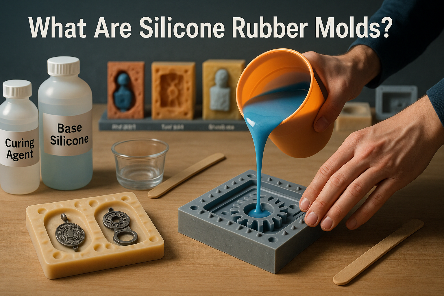
Injection molding is a popular manufacturing method for many reasons. It has proven especially valuable to those in the consumer product development sector, since plastics are a primary component of many consumer products, and injection molding is one of the best ways to manufacture plastics.
Advantages of injection molding
The advantages of injection molding are such that it’s actually one of the most cost-effective means of producing a lot of plastic parts. In addition to being efficient in terms of production time, materials, and labor costs, we recycle some of our post-production plastic waste ourselves.
Because parts can be designed with whatever features are needed—without having to adhere to conventional manufacturing constraints—injection-molded design guidelines are really almost nonexistent. Enjoyment and creativity!
Why Is Draft Angle Important in Injection Molding?
With plastic part design, new designers or engineers consider shape, thickness, and strength—but they sometimes do not consider draft angle. A small feature with major implications on the injection molding process. Lack of draft will cause higher production costs for the manufacturer, more scrap for the molder, & faster mold wear.
1. Ejecting Parts Smoothly
The most important function of draft angle is to ensure that parts eject easily from the mold. All plastics shrink during cooling and cling to the walls of a mold upon solidifying. With straight walls, the part would stick or even possibly bind inside the cavity if it did not have a slight angle (this would be bad). A 1°–2° draft on all mating surfaces prevents this.
2. Limits Damage
When parts stick to the mold, ejector pins have to push harder. This can lead to scratches, drag marks, cracks, or stress lines. In the case of textured or polished surfaces, the danger of visible defects gets even higher. Draft angle minimizes these effects, as it makes sure that there is a low resistance during demolding, which helps keep the quality and appearance of your parts.
3. Extends Mold Life
Injection molds are a big investment, costing thousands of dollars. If parts don’t have draft, the mold will be worn out quickly due to repeated forceful ejection, which leads to less mold life accuracy and shortens the life span of a mold, causing it not to produce as many parts as it should. Draft angle in plastic injection molding reduces stress on a mold and therefore extends its usable life, which means lower costs over time.
4. Saves Production Time and Costs
Cycle time is a vital consideration in injection molding. The longer it takes for parts to eject, the longer production takes. In fact, this time delay can add hours or days to a high-volume production run. By applying draft, parts release faster, keeping cycle times fast and efficient. Faster cycles mean higher productivity and lower per-part costs!
How to Design Draft Angle in Injection Molding (Step by Step)
Designing the draft angle for injection-molded parts is no easy task. But if you take a systematic approach to it, considering factors such as material, part geometry, surface finish, mold release method, etc. you can make a right start. Below is a detailed step-by-step guide on how to design your draft angles properly.
Step 1: Locate all Vertical Surfaces
Firstly, you have to go through your 3D CAD model and look for all the vertical surfaces that will come into contact with the mold cavity or core. This includes side walls, ribs, bosses, and also deep features. Those are mainly the most important elements, as they are close to the mold’s opening direction and will for sure stick to it.
Look for places where a side wall leads to other features. Beginners often overlook drafts in these areas. Also look for hidden features like undercuts, deep holes, or slots. Draft is also often missed by beginners here.
Use your CAD software’s draft analysis tool to give you an indication of where there is no draft. For example, in SolidWorks, green is OK and means your part can be ejected from the mold without any issues. Red or blue, on the other hand, means that there is not enough draft.
Step 2: Define the Parting Line and Pull Direction
The parting line is the line that separates the two halves of the mold. Draft angles are always applied with respect to this pull direction.
For parts that are symmetrical about a plane, it’s desirable to have the parting line be in that symmetry plane. This simplifies part design, as one side of the mold is identical with the other mirrored side and does not require any slides or lifters.
However, for most common symmetric components (such as cups, containers, etc.), you would like to eject them vertically.
Choose Pull Direction: It is important to ensure that the appropriate pull direction of a part is identified; otherwise, it may result in a negative draft, which will trap the part within the mold.
Step 3: Determine Draft Angle Based on Material Properties
Different materials contract differently when cooling and shrinking. Draft angle should be considered according to the resin.
- Low-friction materials like ABS, polypropylene (PP), and polystyrene (PS) require less draft (0.5°–1°).
- High-shrink materials like polyethylene (PE) or nylon may require higher draft (1.5°–2°).
- Elastomers and flexible plastics sometimes need as much as 3° draft because they cling more to the mold.
Step 4: Take Surface Finish and Texture into Account
The smoother finish you want the part to have, the more easily it will come out of the mold. On the other hand, if a texture or rough surface is desired, you will need extra draft to allow for friction.
- For high-gloss polished surfaces you usually get away with 0.5°–1° draft.
- For light matte finishes it is better to have at least a 1°–2° draft.
- For deep textures or grain patterns, add 1.5°–2° draft per 0.001 in. of texture depth.
Step 5: Apply Draft in CAD Software
- Now that you know the required draft angle, you can apply it directly to your 3D model using CAD tools.
- Most CAD systems (SolidWorks, CATIA, Creo, NX, and Inventor) have a “Draft Feature” option.
- Select the surfaces that require draft, choose the neutral plane (usually the parting line), and enter the angle value.
- Apply draft consistently across all similar features to maintain uniformity.
Step 6: Validate Wall Thickness After Drafting
- One of the bigger reasons is drafting can change wall thickness at the top or bottom of the part.
- CAD analysis tools can be used to measure the minimum and maximum wall thickness. Avoiding thin spots will help prevent weak parts or sink marks.
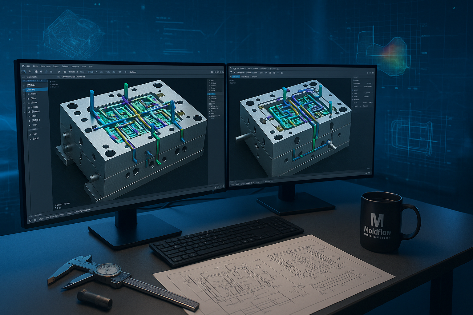
- Run a draft analysis and mold flow simulation to analyze the part design for manufacturing.
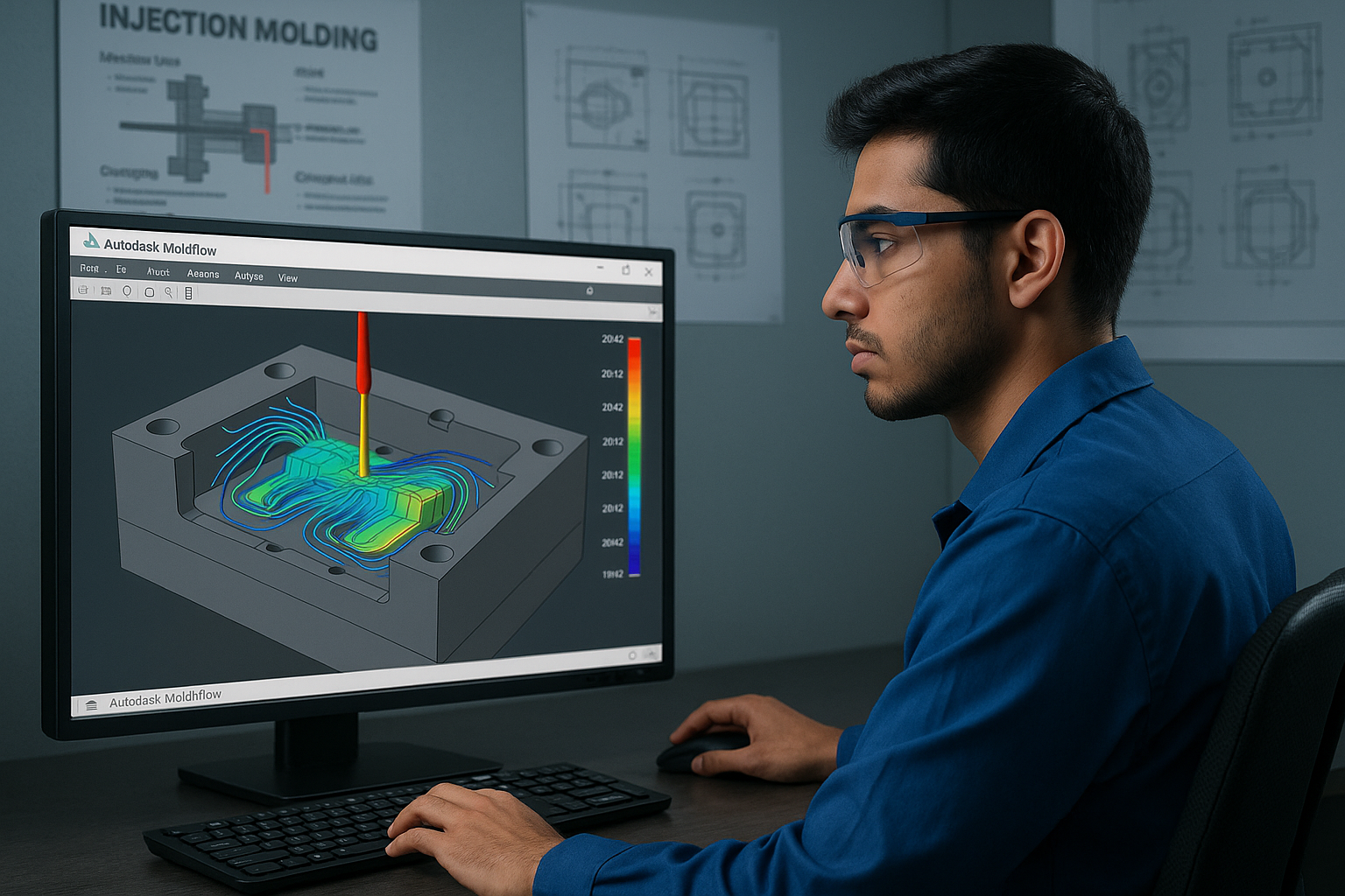
Step 7: Perform Draft Analysis and Moldflow Simulation
- Always, always do a draft analysis before you freeze your design.
- Draft analysis in CAD and Moldflow simulation is used to predict the ejector force, areas under high ejection forces are prone to get flash, as complete parts do not flow till the end when there is high ejector force.
Step 8: Optimize for Ejection System
- This is because the draft angle works with the mold ejection system.
- If the mold uses ejector pins, be sure to add draft, just enough for a good release of the mold without any pin mark.
- An air ejection system maybe can go with a little less, but never no-draft.
- For stripper plates or sleeve ejection (used for cylindrical parts), draft is important to get the product released smoothly.
Conclusion
Designing the draft angle in injection molding is not a small design consideration but one of the most important factors that will determine if plastic part production will be successful. Even the smallest draft of 1°–2° can lead to the difference between an easy production process without defects and late investments in major modifications of the mold or even damages.
By correctly analyzing vertical surfaces, finding the right parting line location, choosing appropriate draft based on material properties, and considering added textures or finishes, designers will secure scratch- and warp-free product ejection from the mold. Usage of CAD programs for draft analysis and simulations takes all guesswork from user’s hands, while optimization of the ejection system guarantees continued reliability.
A well-designed draft angle ensures:
- Smooth and Damage-Free Part Ejection
- Lower production costs and shorter cycle times
- Extended mold life with less wear and maintenance
- Improved part aesthetics and surface quality


0 Comments